Helicopter > Kamov Ka-52
Development and description ot the
coaxial rotor-mechanics Kamov Ka-52
Description of the mechanics CRM-E:
The ZG62 SL gasoline engine drives two counter-rotating rotor shafts, each with its own rotor, via a two-stage reduction gearbox. The inner rotor shaft is a hollow shaft with an outer diameter of 15 mm. The outer rotor shaft is a tubular rotor shaft with an outer diameter of 20 mm. The inner shaft is hollow because it houses the yaw linkage for adjusting the upper rotor head. The counter-rotation of the two rotors is achieved by three spiral bevel gears running in an oil bath. The ZG62 SL gasoline engine is cooled by a radial fan. An electric starter is integrated for easier starting. A freewheel system disengages the starter after the gasoline engine has started.
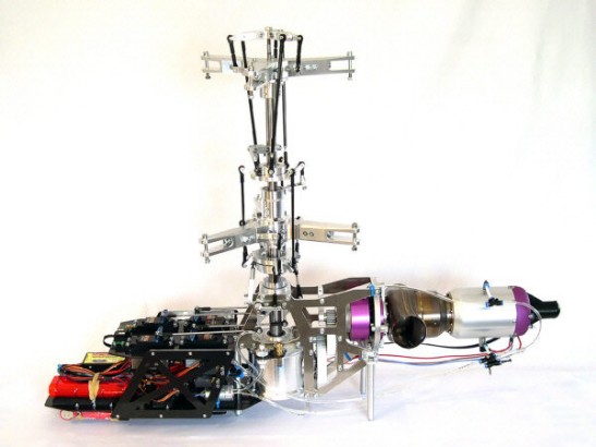
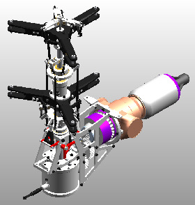
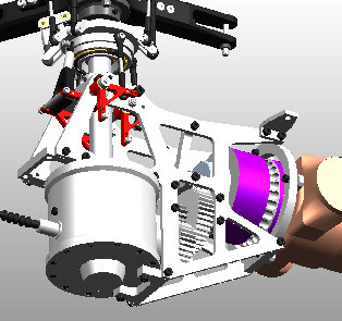
Desription of the mechanics CRM-T
The JetCat SPT5-H twin-shaft turbine drives the two counter-rotating rotor shafts, each with its own rotor, via a two-stage reduction gearbox. Unlike the gasoline-powered version, the turbine in this model is horizontally oriented and drives the counter-rotating gearbox via the aforementioned reduction gearbox.
The entire rotor system, including the two counter-rotating rotors and their control, is otherwise identical to the gasoline-powered CRM-E version.
The gasoline-powered CRM-E version is no longer available.
Only the CRM-T version with the JetCat twin-shaft turbine remains.
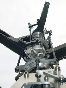
Rotor control:
Cyclic control:
Both rotors have one swashplate for controlling their three rotor blades. The lower rotor blades are controlled directly via the outer ring of the lower swashplate. The upper rotor blades are controlled indirectly via the upper swashplate and the mixing levers located above the upper rotor head. When the lower swashplate is controlled cyclically, the upper swashplate is also directly actuated in the same direction. By carefully selecting the swashplate diameters and mixing lever parameters, the upper and lower rotor systems have identical cyclic deflections.
Collectiv pitch:
Pitch control is applied to both swashplates in the same direction. Raising or lowering the lower swashplate directly controls the upper one. However, due to the aforementioned mixing levers, the upper rotor head experiences a greater deflection at the blade grips. This creates a yaw moment on the helicopter, which is easily compensated for by a static "tail rotor" mix on the transmitter in conjunction with a yaw gyro or 3-axis stabilization.
Yaw control:
The yaw control of the rotor system is achieved by applying opposing pitch control to the two rotor heads. Different lift values are generated at the two rotors, resulting in different torques that cause the helicopter to yaw around its vertical axis. The resulting lift at both rotors remains the same, preventing the model from climbing or descending simultaneously. The yaw control (tail rotor function) is actuated by axially adjusting the mixing lever bridge, to which the mixing levers are mounted. The mixing lever bridge is actuated by the yaw servo via a sliding sleeve/baffle combination through the hollow inner rotor shaft. This actuation directly controls only the blade grips of the upper rotor head. Conversely, a transmitter-side mix lowers or raises the lower swashplate.
Reproduction only with the author's permission. All information is provided without guarantee.